Handling (Unloading at site) : On receipt of cable drums visual inspection of drums should be made ensuring drum packing is original. While unloading the cables certain precautions are to be taken to ensure the safety of the cables.

Storage:
Cables should be stored in a dry covered place to prevent exposure to climatic conditions and wear and tear of wooden drums and it should preferably on a concrete surface/firm surface which will not cause the drums to sink and thus lead to flange rot and extreme difficulty in moving the drums.
All drums should be stored in such a manner as to leave sufficient space between them for air circulation. It is desirable for drums to stand on battens placed directly under the flanges.
In no case should the drums be stored, “On the Flat”, i.e., with flange horizontal.

Laying:
For laying of cables special cares to be taken to prevent sharp bending, kinking, twisting. Cable should be unwound from drum by proper mounting the cable drum on a cable wheel making sure the spindle is strong enough to carry the weight without bending and that it is lying horizontally in the bearings so as to prevent the drum creeping to one side or the other while it is rotating.
Provision should be made to break the drum to avoid further rolling & buckling of cable during sudden stop. A simple wooden plank can server this purpose

Cable must be puled from the top
This is incorrect way of pulling the cable & will cause kinks & twist in cable. Shall be avoided at all

Cable must be pulled across hard & sharp objects to avoid the damage to ve covering & insulation
Cable must be laid in ducts or trenches as shown in Fig.

However, following salient points are to be considered during laying procedure of cables laid in racks and in built-in trenches.
1. For laying of cables power cables to be placed at the bottom most layer and control cables at top most layer.
2. Single core power cable for use on A.C. system shall be laid in delta formation supported by non-magnetic material. Trefoil clamps of suitable size are to be placed at regular intervals but preferably not more than 800 mm. Axial spacing of two circuits in delta formation shall not be less than 4 times the cable dia.
In case of multicore power cables, cables shall be laid side by side, with spacings not less than one cable diameter. However derating factors for cables laid on trenches are to be referred.
Multicore power cables and single core D.C. circuits may be clamped by means of galvanised mild steel saddles but 1.1 KV single core cables should be clamped by means of non-magnetic saddles. The saddles shall not be placed at intervals more than 1500 mm. for horizontal and 1200 mm. for vertical runs.
3. Multicore control cables can be laid touching each other on cable racks and wherever required may be taken in two layers. They should be clamped by means of PVC straps both for horizontal and vertical runs (alternatively, fabricated aluminium clamps may be used) at regular intervals.
4. a) If the cables are buried directly in ground I.S. 1255 is to be followed for code of practice. However, generally cables are laid 1000 mm. below finished ground level at any point of cable run and 75 mm. of sand cushioning to be provided.
4. b) In loose soil concrete pillar should be provided for as support and hence pipes are recommended to the used for cable path.
5. If there is a possibility of mechanical damage, cables should be protected by means of mild steel covers placed on racks.
6. While laying cables, special care to be taken at bends. Followings are the recommended bending radius for power and control cables.
| Voltage Rating KV | PVC and XLPE Cables | |
| Single Core | Multi Core | |
| Upto 1.1 Above 1.1 but upto 11K.V. Above 11 K.V. | 15 D | 12 D |
| 15 D | 15 D | |
| 20 D | 15 D | |
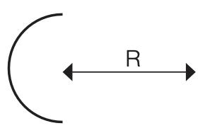
Where ‘D’ is overall diameter of cable.
7. Maximum safe pulling force (when pulled by pulling eye) Aluminium Conductor Cables : 3.0 Kg/mm2 Copper Conductor Cables : 5.0 Kg/mm2 Proper method of pulling of cable should be used.
TESTING
INSULATION RESISTANCE MEASUREMENT OF CABLE
The voltage rating of I.R. Tester (Megger) should be chosen as following table:
| Voltage grade of cable | Rating of IR Tester (Megger) of cable | Voltage grade of cable | Rating of IR Tester (Megger) |
| 1.1 KV | 500 V | 11 KV | 1000V |
| 3.3 KV | 1000V | 22 KV | 2500 V |
| 6.6 KV | 1000V | 33 KV | 2500 V |
Testing during laying :
All new cables shall be megger-tested before jointing. After jointing is completed all LV Cables shall be megger-tested.
End Terminations & Jointing :
Termination and jointing of Power & Control Cables shall be done by means of compression methods using solderless tinned copper/ Aluminium terminal lugs. For control cables terminations, ring tongue or reducer pin type terminal lug can also be used to suit the purpose.
Overhead/Outdoor Termination
XLPE insulation should be protected from direct solar rays or else ultra violet resistant sleeving / tapping must be provided on exposed XLPE insulation at the Termination to avoid degradation / cracking due to direct exposer of solar rays.